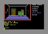
Last time I’ve talked about memory issues, and I must think through again how to resolve this problem. The original game fits complete into the basic memory, and even there’s 8kb left free. Before I start kicking some code out, mainly comments, I’ve tried to squeeze in the last string resources for the interpreter response messages, and I’ve succedeed. Now there are only 369 bytes free; terrific, but where I’m going to put the whole interpreter? Switching to dumb strategy: do whatever you’re in the mood for doing, and that surely ain’t writing a text adventure interpreter in BASIC in just 369 bytes.
Therefore, it’s time for some C64 assembler. I’m very excited about this topic; last time I’ve did assembler on PC was 12 years, and on C64 about 20 years ago. The 6502 processor has a very limited instructions set listed here. There are a couple of more things that makes coding even harder, for example, only 3 registers, no instructions for multiplication and division, 8bit data… The good news are that you don’t have to code on a C64 thanks to cross assemblers and they have many useful functions for organizing code, importing data, automatically building and debugging code on a emulator.
After researching a while I’ve decided to use KickAssembler. It has all the options needed, and it can be easily integrated into the text editor I’m using, with syntax highlighting and code building; it even supports variables and java script like language. All the features are listed in the KickAssembler manual here. And for better C64 understanding I would strongly suggest this book here.
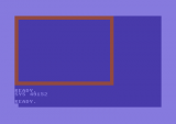
The main problem is the UI drawing in the game; it’s slow, but before you draw anything, you also have to clear some parts of the screen. Since the room drawing depends on room state data which can’t be easily passed to assembler subroutines, and same goes for printing items and directions, the thing what could make sense is first to code routines for drawing the frame and clearing stuff on the screen. Items and directions are printed more-less at a descent speed. Time to see some assembler code:
// include basic upstart
.pc = $0801 “BASIC”
:BasicUpstart($c000)
// code start address
.pc = $c000 “Maya Grab”
The code starts with two .pc directives which tell the compiler where the code should be stored in memory while loading. The first directive has a small convinience method which tells the compiler to include a BASIC startup code to call the machine code at address $c000. I’ve mentioned that on the second day of the journal that most games written complete in assembler have only one basic line with a call to the actual machine code. I’ve included that only for faster testing.
// zeropage pointers
.const screen = $fb
.const param1 = $fd
.const param2 = $fe
// constants
.const CHAR_FRAME = 160
.const CHAR_CLEAR = 32
.const FRAME_COLOR = 2
.const FRAME_WIDTH = 27
.const FRAME_HEIGHT = 18
The zeropage pointers are simply pointers to a memory address on page zero (first 256 bytes). They are used very often because only the low byte must be set when addressing (high byte is always zero in $00fb, $00fd and $00fe). I don’t think that this zeropage space is meant to be used for storing any data (lot’s of kernal stuff is placed there), and I’ve read somewhere that BASIC uses most of the addresses too, but these few at the end are pretty much safe. Other constants are self explanatory.
/*******************************
* Draw Frame
*******************************/
DrawFrame:
ldx #00
!loop_x:
lda #CHAR_FRAME
sta $0400,x
sta $0400+FRAME_HEIGHT*40,x
lda #FRAME_COLOR
sta $D800,x
sta $D800+FRAME_HEIGHT*40,x
inx
cpx #FRAME_WIDTH
bne !loop_x-
This is the first part of the draw frame routine for drawing the horizontal bars at the top and bottom of the frame. While in BASIC you can change the text color directly in the PRINT command, in assembler things are a little bit different. Printing a char on screen is the same as putting a byte into the screen memory, which by default is beginning from address $0400. But there is also a color ram which holds the colors for every char on screen and it’s located at address $D800. So this routine loads the char (reverse space) first and stores it at $0400 and then the char color (red) and stores it at $D800, both with an offset which is stored in register X.
lda #$04
sta screen+1
lda #$28
sta screen
lda #$D8
sta param2
lda #$28
sta param1
ldx #00
The second part of the routine is preparing everything for rendering the side bars. The screen address and the color ram address are loaded as hi/lo bytes and stored into the previously defined pointers. Since we’re dealing with a 8bit machine, we can’t do something like lda #$0428 or lda #$D800.
ldx #00
!loop_y:
pha
lda #CHAR_FRAME
ldy #00
sta (screen),y
ldy #FRAME_WIDTH–1
sta (screen),y
lda #FRAME_COLOR
ldy #00
sta (param1),y
ldy #FRAME_WIDTH–1
sta (param1),y
pla
clc
adc #40
bcc !no_carry+
inc screen+1
inc param2
!no_carry:
sta screen
sta param1
inx
cpx #FRAME_HEIGHT–1
bne !loop_y-
rts
The final part now is a little bit complicated. First the counter in register X is reseted. Next, while writing one char and it’s color left and right for the bars, the register A is needed and therefore it must be saved first on the stack with the PHA command and later reloaded with PLA. Now the 8bit limitation strikes! To render the next line, we can’t just add an offset of 40 bytes and continue looping. The value of the A register can be 240 and adding just 40 would exceed 8 bits. Luckily, the processor has a carry flag which is set when overflow occurs while doing operations. First it needs to be cleared with CLC, then 40 bytes are added to the offset; if the carry is set, we need to update the hi byte in our screen and color ram addresses, otherwise we’re updating only the lo bytes.
/*******************************
* Clear Screen Part
* in: screen = pointer start
* param1 = width
* param2 = height
*******************************/
ClearScreenPart:
ldx #00
!loop_y:
ldy #00
pha
!loop_x:
lda #CHAR_CLEAR
sta (screen),y
iny
cpy param1
bne !loop_x-
pla
inx
cpx param2
beq !clear_done+
clc
adc #40
bcc !no_carry+
inc screen+1
!no_carry:
sta screen
jmp !loop_y-
!clear_done:
rts
This routine simply draws a rectangle of spaces into the screen memory and it uses the same carry flag principle as the draw frame routine. But before calling it, parameters must be set as follows: screen is pointing already at the position where the rectangle starts and param1 and param2 are used for the width and the height of the rectangle.
ClearRoom:
lda #25
sta param1
lda #17
sta param2
lda #$04
sta screen+1
lda #$29
sta screen
jsr ClearScreenPart
rts
An example how the ClearScreenPart routine is used for clearing the contents inside the frame.
The complete source code of all routines in assembler is included.
Program size: 38542 bytes, on disk 36322 bytes or 143 blocks
Free BASIC memory: 369 bytes
Used BASIC commands: –


